Air-Driven High Pressure Pump
AHP2500
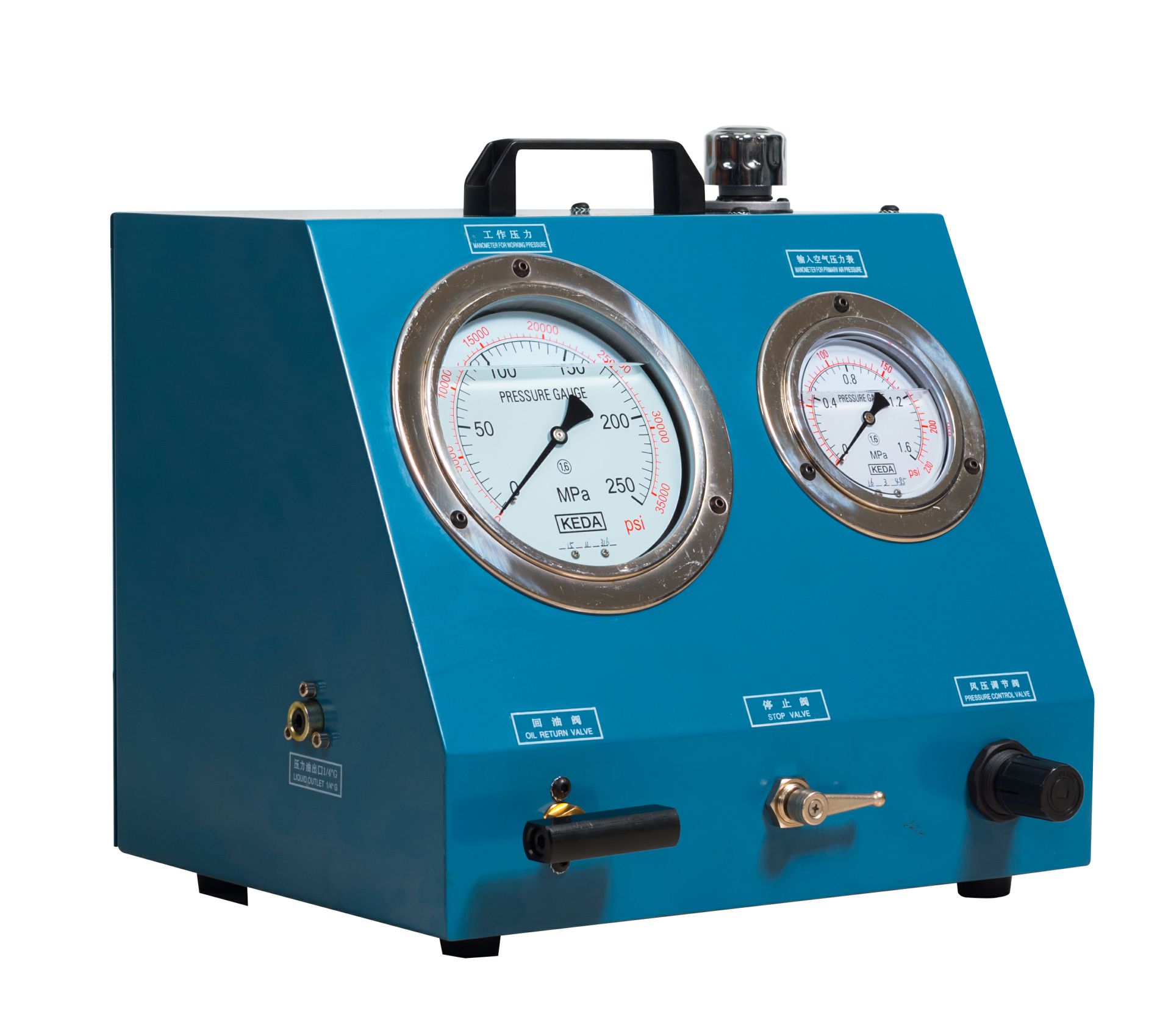
The various control instruments and maneuvering handles are
fitted with a number.these numbers are mentioned in this instruction
and are also referring to the numbers found on the drawings showing
the complete pump unit.
Furthermore,these numbers are found on the instrument panel of the
pump unit Please,read this direction of use carefully before using
the pump unit and follow the instructions given very carefullyof the
working principles of the pump unit
(Note: Be sure to fill up with oil before using)
Note: This device is suitable for use with a single hydraulic tool
BEFORE CONNECTING THE PUMP UNIT:
The tank is filled with oil through the filler cap(6)in the right
side of the top panel.Oil;Any good hydraulic oil may be used.
a ) Open oil return valve(1)by turning anti-clockwise.
b ) The handle of the regulator valve(3)should be turned 4-5
turns anti-clockwise.This is done to avoid the pump starting at atoo high pressure level.
c )Stop valve(2)should be turned clockwise,to close the
valve.This is done to ensure that the pump will not work at will when the primary pneumatic system is connected
CONNECTION OF PUMP:
Compressed air is led through a flexible hose and is connected to the stud marked"air inlet"(7)on the right side of the cabinet.This stud has an1/2B.S.P.female thread. The hydraulic system is connected to the stud marked"high pressure outlet"(8)found on the left side of the cabinet.This stud has a 1/4B.S.P.female thread.The pump is now ready for use.The pump may also be operated by hand if compressed air is not available.A handle(9) is placed in a retainer on the top panel.It may easily be fitted to the pump through the slot in the slot in the left side plate by pressing it into the bushing found inside the slot.
START OF PUMP:
a )Stop valve(2)is turned slowly anti-clockwise,where
by compressed air enters into the pump unit,which
commences to work.The stop valve(2)is also acting as a regulator valve for the pumping speed.
b )The regulator valve(3),which is used for adjusting the
pressure is now turned clockwise and the hydraulic pressure may now be read on the manometer for pressure control(4).This manometer shows the hydraulic high pressure in bar.
c )The oil return valve(1)is closed by turning the knob clockwise and the oil will then run from the oil tank into the hydraulic system.When the hydraulic system has been filled,and the pump has stopped operating,the high pressure reached can be read at the manometer for workingpressure(5)found on the left side of the instrument panel.The pump stops automatically,when the required high pressure has been established and holds it infinitely.The Pump starts automatically again if a pressure drop occurs in the hydraulic system.
d )High pressure may be removed from the system by the opening the oil return valve(1)(to be turned anti-clockwise).The excessive oil in the secondary high pressure system will thereby return to the oil tank in the pump unit.
ENDING OF JOB:
To avoid oil spillage,precautions should be taken to see that the Oil is taken back into the oil tank before the connections on the high pressure side are disconnected.This is done by turning the oil return valve(1)anticlockwise.Simultaneously the pump should be stopped by turning the stop valve(2)clockwise,and when this valve has been closed,the air hose may be removed and the pump transferred to another job.

Air-Driven High Pressure Pump-AHP2500
Currently only available: $1000 (Adjusted according to exchange rate fluctuations)
Welcome to purchase
You can contact us by email


